
TM 5-2410-240-23-2
0039
REMOVAL CONTINUED
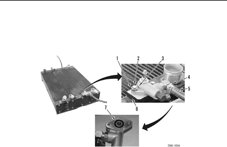
29. Loosen clamp (Figure 11, Item 4) and disconnect hose (Figure 11, Item 5) from drain valve (Figure 11, Item 3).
30. Remove clamp (Figure 11, Item 4) from hose (Figure 11, Item 5).
31. Remove two bolts (Figure 11, Item 2), spacers (Figure 11, Item 1), and drain valve (Figure 11, Item 3), from
core assembly (Figure 11, Item 6).
32. Remove O-ring (Figure 11, Item 7) from drain valve (Figure 11, Item 3). Discard O-ring.
Figure 11. Drain Valve.
0039
END OF TASK