
TM 5-2410-240-23-2
0039
INSTALLATION CONTINUED
WARN I N G
Use extreme caution when handling heavy parts. Provide adequate support and use
assistance during procedure. Ensure any lifting device used is in good condition and of
suitable load capacity. Keep clear of heavy parts supported only by lifting device. Failure
to follow this warning may cause injury or death to personnel.
N OT E
Core assembly weighs approximately 225 lb (102 kg).
Install bolts and washers as noted during removal.
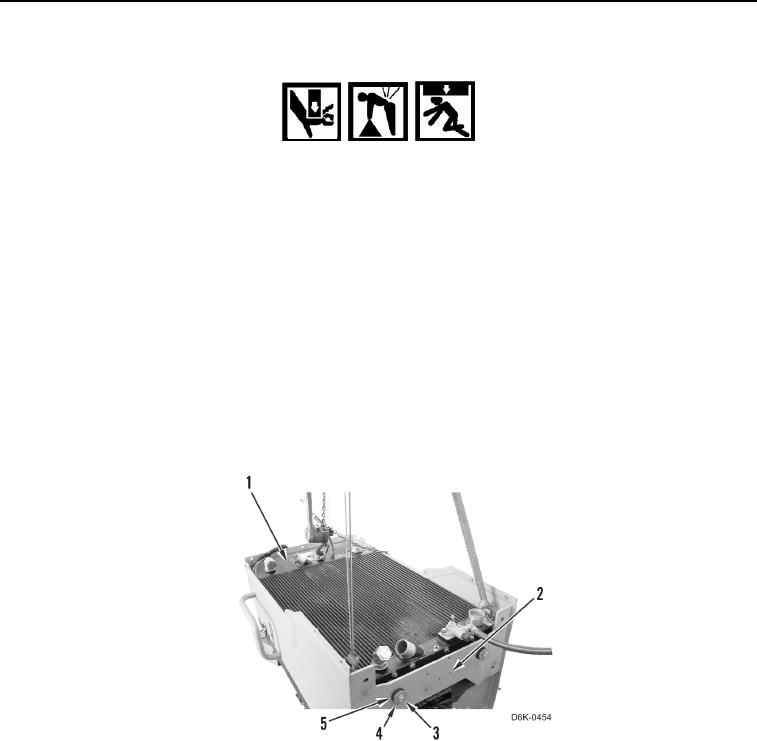
5. Install lifting device on core assembly (Figure 15, Item 1).
6. Using lifting device and assistance, install core assembly (Figure 15, Item 1) on cooling module (Figure 15,
Item 2).
7. Install two rubber mounts (Figure 15, Item 5), four washers (Figure 15, Item 4), and two bolts (Figure 15,
Item 3), on cooling module (Figure 15, Item 2).
8. Remove lifting device from core assembly (Figure 15, Item 1).
Figure 15. Core Assembly and Cooling Module.
0039