
TM 5-2410-240-23-2
0068
REMOVAL CONTINUED
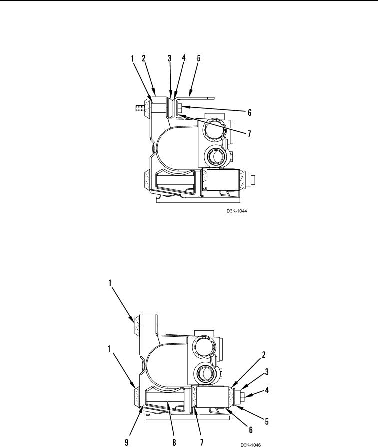
7. Remove bolt (Figure 4, Item 6), washer (Figure 4, Item 7), bracket (Figure 4, Item 5), washer (Figure 4, Item 4),
isolation mount (Figure 4, Item 3), and spacer (Figure 4, Item 1) from base (Figure 4, Item 2).
Figure 4. Fuel Prime Pump and Base Assembly.
0068
8. Remove two bolts (Figure 5, Item 4), two spacers (Figure 5, Item 3), two washers (Figure 5, Item 5), two
isolation mounts (Figure 5, Item 2), bracket (Figure 5, Item 6), two isolation mounts (Figure 5, Item 7), two
spacers (Figure 5, Item 8), base (Figure 5, Item 9), and three isolation mounts (Figure 5, Item 1) from machine.
Figure 5. Primary Fuel Filter Base Assembly.
0068