
TM 5-2410-240-23-2
0075
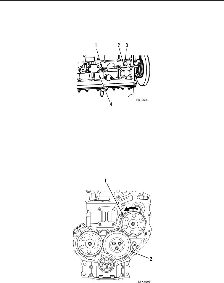
FUEL INJECTION PUMP GEAR REMOVAL CONTINUED
2. Remove plug (Figure 2, Item 3) and O-ring (Figure 2, Item 2) from cylinder block (Figure 2, Item 4). Discard
O-ring.
3. Install adapter and crankshaft timing pin in access hole (Figure 2, Item 1).
Figure 2. Crankshaft Timing Pin.
0075
N OT E
Fuel injection pump must remain locked until procedure instructs to unlock the fuel pump.
4. Lock fuel injection pump shaft in position.
5. Apply pressure to fuel injection pump gear (Figure 3, Item 1) in a counterclockwise direction as shown in
(Figure 3).
6. Mark position of three gears (Figure 3, Item 2) in order to show alignment during installation.
Figure 3. Fuel Injection Pump Gear.
0075