
TM 5-2410-240-23-2
0075
FUEL INJECTION PUMP REMOVAL
00075
N OT E
Tag wiring harness to aid installation.
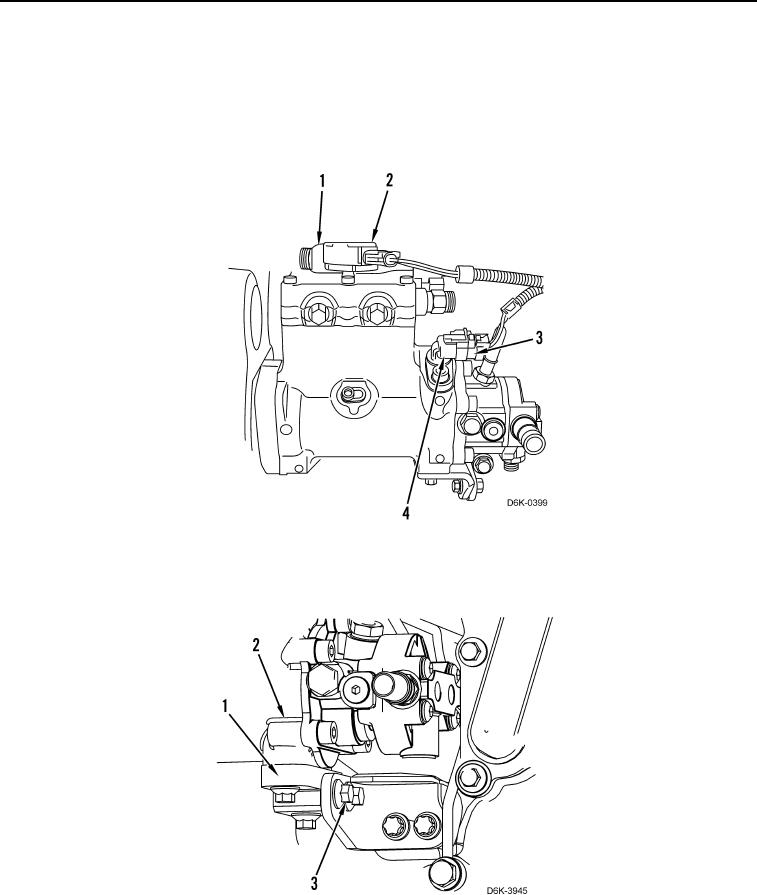
1. Disconnect harness connector (Figure 6, Item 2) from solenoid (Figure 6, Item 1).
2. Disconnect harness connector (Figure 6, Item 3) from position sensor (Figure 6, Item 4).
Figure 6. Fuel Injection Pump Lines/Connectors.
0075
3. Remove four bolts (Figure 7, Item 3) and support bracket (Figure 7, Item 1) from fuel injection pump (Figure 7,
Item 2).
Figure 7. Fuel Injection Pump Support Bracket.
0075