• Home
  • Download PDF
  • Order CD-ROM
  • Order in Print
Figure 10. Fuel Injection Pump.
Figure 13. Front Gear Set Timing Marks.

Field Maintenance Manual 2 D6K Dozer Type I With Winch and Type II With Ripper
Page Navigation
  330    331    332    333    334  335  336    337    338    339    340  
img
.
TM 5-2410-240-23-2
0075
FUEL INJECTION PUMP INSTALLATION CONTINUED
N OT E
Install wiring harnesses as tagged during removal.
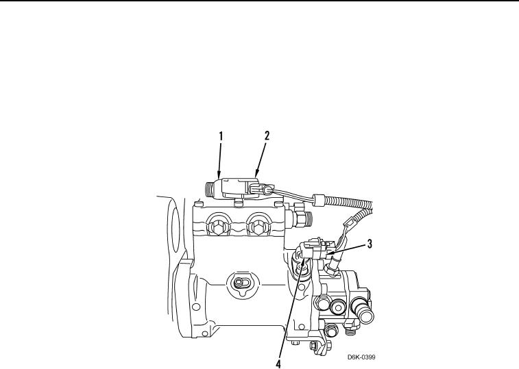
9. Connect harness connector (Figure 12, Item 2) on solenoid (Figure 12, Item 1).
10. Connect harness connector (Figure 12, Item 3) on position sensor (Figure 12, Item 4).
Figure 12. Fuel Injection Pump Lines/Connectors.
0075
END OF TASK
0075-10


Privacy Statement
Press Release
Contact

© Copyright Integrated Publishing, Inc.. All Rights Reserved.