
TM 5-2410-240-23-2
0075
FUEL INJECTION PUMP GEAR INSTALLATION CONTINUED
4. Loosen locking screw (Figure 15, Item 2) on fuel injection pump (Figure 15, Item 1).
N OT E
Slide locking washer into correct position to prevent the locking screw from tightening
against shaft of fuel injection pump.
5. Slide locking washer (Figure 15, Item 3) forward.
6. Tighten locking screw (Figure 15, Item 2).
Figure 15. Fuel Injection Pump Shaft Lock.
0075
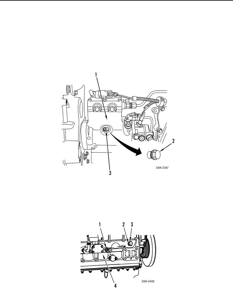
7. Remove crankshaft timing pin and adapter from engine block access hole (Figure 16, Item 1).
8. Install new O-ring (Figure 16, Item 2) on plug (Figure 16, Item 3).
9. Install plug (Figure 16, Item 3) on engine block (Figure 16, Item 4). Tighten plug to 66 lb-ft (90 Nm).
Figure 16. Crankshaft Timing Pin.
0075