
TM 5-2410-240-23-2
0075
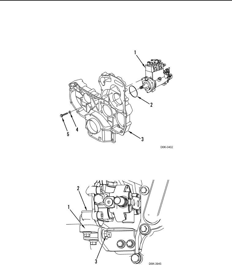
FUEL INJECTION PUMP INSTALLATION CONTINUED
4. Lubricate new O-ring (Figure 10, Item 2) with O-ring assembly compound.
5. Install new O-ring (Figure 10, Item 2) on fuel injection pump (Figure 10, Item 1).
6. Install fuel injection pump (Figure 10, Item 1) on front housing (Figure 10, Item 3).
7. Install three new sealing washers (Figure 10, Item 4) and bolts (Figure 10, Item 5) on fuel injection pump
(Figure 10, Item 1). Tighten bolts to 18 lb-ft (25 Nm).
Figure 10. Fuel Injection Pump.
0075
8. Install support bracket (Figure 11, Item 1) and four bolts (Figure 11, Item 3) on fuel injection pump (Figure 11,
Item 2). Tighten bolts to 16 lb-ft (22 Nm).
Figure 11. Fuel Injection Pump Support Bracket.
0075