
TM 5-2410-240-23-2
0075
FUEL INJECTION PUMP GEAR INSTALLATION CONTINUED
N OT E
Ensure timing marks on gears are in alignment and mesh of gears are correct.
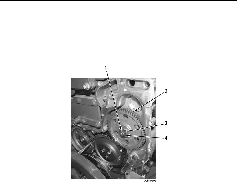
2. Install nut (Figure 14, Item 4) and new lockwasher (Figure 14, Item 3) on fuel injection pump shaft
(Figure 14, Item 1). Tighten nut to 18 lb-ft (25 Nm).
3. Insure timing marks on gears (Figure 14, Item 2) are in alignment.
Figure 14. Fuel Injection Pump Gear Replacement.
0075