
TM 5-2410-240-23-2
0077
INSTALLATION CONTINUED
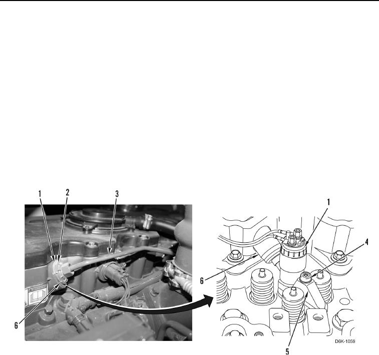
5. Install new cylinder sleeve (Figure 8, Item 6) on fuel injector (Figure 8, Item 1). Ensure that flange of seal is
flush with valve cover base.
C AU T I O N
Ensure the ends of the fuel injection line are seated in the fuel injector and fuel manifold.
Failure to follow this caution may cause engine damage.
N OT E
Install lines as tagged at removal.
Fuel injection lines must only be used once. Discard all fuel injection lines after use.
6. Install new seal (Figure 8, Item 2) and loosely install new fuel injector line (Figure 8, Item 3) on fuel injector
(Figure 8, Item 1).
7. Tighten machine bolt (Figure 8, Item 4) on injector clamp (Figure 8, Item 5) to 20 lb-ft (27 Nm).
8. Tighten fuel injection line (Figure 8, Item 3) to 22 lb-ft (30 Nm).
Figure 8. Fuel Injector Fuel Line Replacement.
0077