• Home
  • Download PDF
  • Order CD-ROM
  • Order in Print
Figure 11. Oil Line and Gasket.
Figure 13. Turbocharger, Gasket, and Exhaust Manifold.

Field Maintenance Manual 2 D6K Dozer Type I With Winch and Type II With Ripper
Page Navigation
  369    370    371    372    373  374  375    376    377    378    379  
img
.
TM 5-2410-240-23-2
0079
INSTALLATION CONTINUED
N OT E
Remove caps from hose end and air inlet elbow prior to installation.
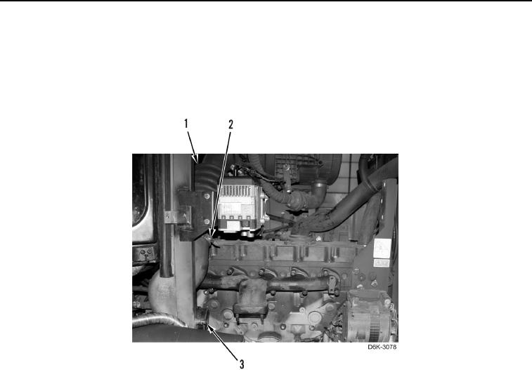
5. Install air inlet elbow (Figure 12, Item 3) on hose (Figure 12, Item 1) and tighten clamp (Figure 12, Item 2).
Figure 12. Air Inlet Elbow and Hose.
0079
0079-13


Privacy Statement
Press Release
Contact

© Copyright Integrated Publishing, Inc.. All Rights Reserved.