
TM 5-2410-240-23-2
0079
INSTALLATION CONTINUED
N OT E
Install hoses as noted during removal.
Remove caps from hose ends.
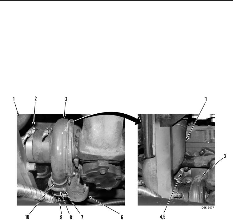
11. Position air inlet elbow (Figure 16, Item 1) on engine.
12. Install three washers (Figure 16, Item 5) and bolts (Figure 16, Item 4) retaining air inlet elbow (Figure 16,
Item 1) on engine.
13. Install hose (Figure 16, Item 10) on turbocharger (Figure 16, Item 3) and tighten two clamps (Figure 16,
Item 9).
14. Install hose (Figure 16, Item 8) and clamp (Figure 16, Item 7) on wastegate (Figure 16, Item 6).
15. Tighten clamp (Figure 16, Item 2).
Figure 16. Turbocharger and Wastegate.
0079