
TM 5-2410-240-23-2
0079
INSTALLATION CONTINUED
N OT E
Install oil line and drain tube as noted during removal.
Remove caps from oil line and drain tube prior to installation.
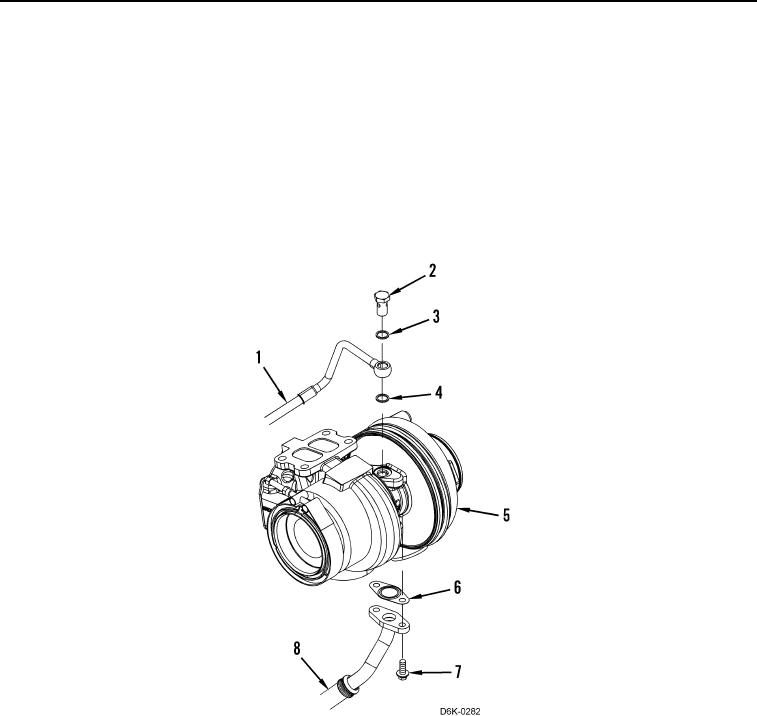
9. Install new washer (Figure 15, Item 4), oil line (Figure 15, Item 1), new washer (Figure 15, Item 3), and fluid
passage bolt (Figure 15, Item 2) on turbocharger (Figure 15, Item 5). Torque fluid passage bolt to
14 lb-ft (19 Nm).
10. Install new gasket (Figure 15, Item 6), drain tube (Figure 15, Item 8), and two bolts (Figure 15, Item 7) on
turbocharger (Figure 15, Item 5). Torque bolts to 16 lb-ft (22 Nm).
Figure 15. Turbocharger.
0079