
TM 5-2410-240-23-2
0100
INSTALLATION
000100
N OT E
Make sure two dowels on oil pump housing align correctly with mating holes on cylinder
block.
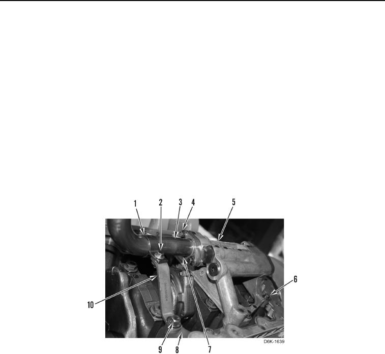
1. Install oil pump (Figure 2, Item 5) on cylinder block (Figure 2, Item 8).
2. Install four bolts (Figure 2, Item 6) retaining oil pump (Figure 2, Item 5) on cylinder block (Figure 2, Item 8).
Torque bolts to 16 lb-ft (22 Nm).
3. Loosely install bracket (Figure 2, Item 10) and bolt (Figure 2, Item 9) on cylinder block (Figure 2, Item 8).
4. Install pipe clip (Figure 2, Item 1) on suction pipe (Figure 2, Item 3).
5. Install new gasket (Figure 2, Item 7) and suction pipe (Figure 2, Item 3) on oil pump (Figure 2, Item 5).
6. Install two bolts (Figure 2, Item 4) retaining suction pipe (Figure 2, Item 3) on oil pump (Figure 2, Item 5).
Torque bolts to 16 lb-ft (22 Nm).
7. Install pipe clip (Figure 2, Item 1) and bolt (Figure 2, Item 2) on bracket (Figure 2, Item 10). Tighten bolts
(Figure 2, Items 2 and 9).
Figure 2. Oil Pump, Suction Pipe, and Retaining Hardware.
0100
END OF TASK