
TM 5-2410-240-23-2
0102
INSTALLATION CONTINUED
C AU T I O N
Install pushrods with cup facing upward. Ensure ball end is correctly seated in valve lifter.
N OT E
Install push rods as noted in removal.
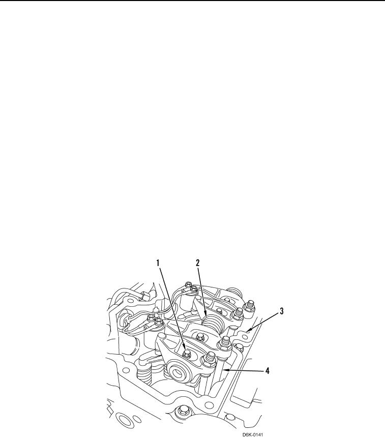
2. Lubricate 12 pushrod ends with clean engine oil and install pushrods (Figure 4, Item 4) on cylinder head
(Figure 4, Item 3).
3. Install machine bolts (Figure 4, Item 1) on rocker shaft (Figure 4, Item 2).
C AU T I O N
When positioning rocker shaft assembly, retaining clip at end of shaft should face toward
the front of engine.
N OT E
Ensure adjustment screws are properly seated in cup ends of pushrods.
4. Position rocker shaft assembly (Figure 4, Item 2) on cylinder head (Figure 4, Item 3).
5. Alternately tighten rocker arm machine bolts (Figure 4, Item 1) 1/2 turn at a time working from center of rocker
arm shaft (Figure 4, Item 2) toward each end. Tighten machine bolts to 26 lb-ft (35 Nm).
Figure 4. Rocker Shaft Replacement.
0102