
TM 5-2410-240-23-2
0102
WARN I N G
Allow engine to cool off before performing maintenance on engine. Hot metal parts can
cause severe burns. Wear eye, hand, and skin protection when working with heated parts.
Failure to follow this warning may cause injury to personnel.
REMOVAL
000102
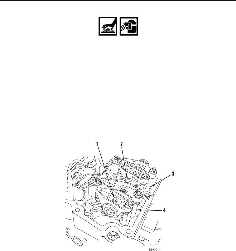
1. Alternately loosen 12 rocker arm machine bolts (Figure 1, Item 1) 1/2 turn at a time, working from each end of
rocker arm shaft (Figure 1, Item 2) toward center.
2. Remove 12 machine bolts (Figure 1, Item 1) from rocker shaft assembly (Figure 1, Item 2).
3. Remove rocker shaft assembly (Figure 1, Item 2) from cylinder head (Figure 1, Item 3).
C AU T I O N
Mark pushrods with location information so they can be reinstalled in original locations. Do
not interchange positions of used pushrods.
4. Mark and remove 12 pushrods (Figure 1, Item 4) from cylinder head (Figure 1, Item 3).
Figure 1. Rocker Shaft Replacement.
0102