
TM 5-2410-240-23-2
0113
SPROCKET GUARD INSTALLATION
000113
N OT E
The following procedure is for right outer sprocket guard. Use the same procedure for right
inner, left inner, and left outer sprocket guards.
Install square spacers as noted in removal. Beveled surface of spacer must be installed
toward weld.
Install bolts and washers in proper location as noted during removal.
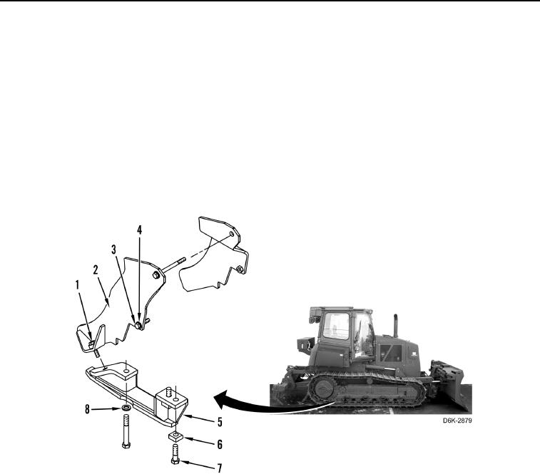
1. Install lower outer sprocket guard (Figure 6, Item 5), washer (Figure 6, Item 8), two spacers (Figure 6, Item 6),
and three bolts (Figure 6, Item 7) on machine.
2. Install upper outer sprocket guard (Figure 6, Item 2), two spacers (Figure 6, Item 1), washer (Figure 6, Item 4),
and three bolts (Figure 6, Item 3) on machine.
Figure 6. Sprocket Guard.
0113
END OF TASK