
TM 5-2410-240-23-2
0113
SPROCKET GUARD REMOVAL
000113
N OT E
The following procedure is for right outer sprocket guard. Use the same procedure for right
inner, left inner, and left outer sprocket guards.
Note position of square spacers to aid installation. Beveled surface of spacer must be
installed toward weld.
Note size and location of bolts and washers to aid installation.
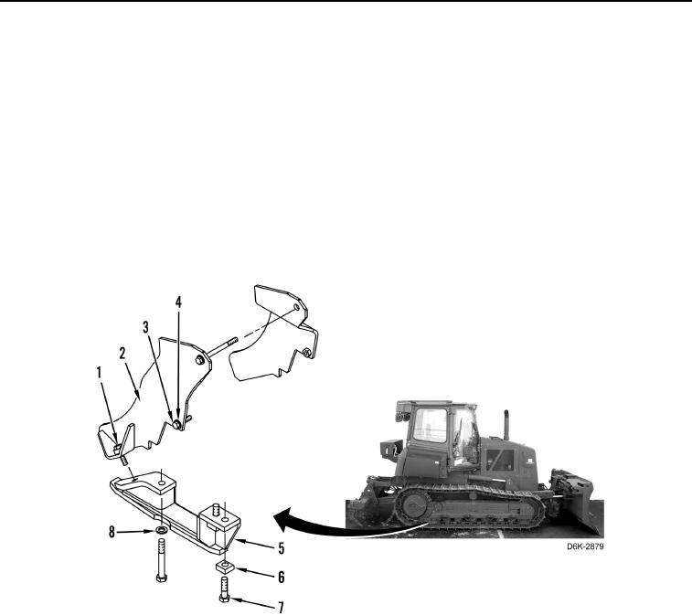
1. Remove three bolts (Figure 5, Item 3), washer (Figure 5, Item 4), two spacers (Figure 5, Item 1), and upper
outer sprocket guard (Figure 5, Item 2) from machine.
2. Remove three bolts (Figure 5, Item 7), two spacers (Figure 5, Item 6), washer (Figure 5, Item 8), and lower
outer sprocket guard (Figure 5, Item 5) from machine.
Figure 5. Sprocket Guard.
0113
END OF TASK
CLEANING AND INSPECTION
000113
Clean and inspect all parts IAW Mechanical General Maintenance Instructions (WP 0282).
END OF TASK