
TM 5-2410-240-23-2
0112
TRACK ADJUSTMENT CONTINUED
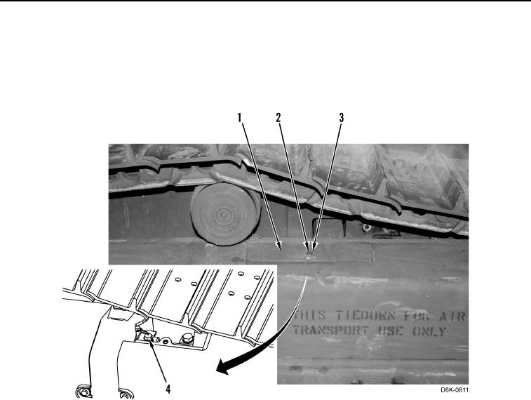
4. Remove bolt (Figure 18, Item 2), washer (Figure 18, Item 3), and plate (Figure 18, Item 1) from machine.
5. Rotate valve (Figure 18, Item 4) counter-clockwise, allowing grease to escape until track tension meets
specification 1.4 0.24 in. (35 6 mm).
6. Install plate (Figure 18, Item 1), washer (Figure 18, Item 3), and bolt (Figure 18, Item 2) on machine.
Figure 18. Track Tension Adjustment.
0112
END OF TASK
FOLLOW-ON TASKS
000112
Verify correct operation of machine (TM 5-2410-240-10).
END OF TASK
END OF WORK PACKAGE
0112-17/(18 blank)