
TM 5-2410-240-23-2
0112
TRACK ADJUSTMENT CONTINUED
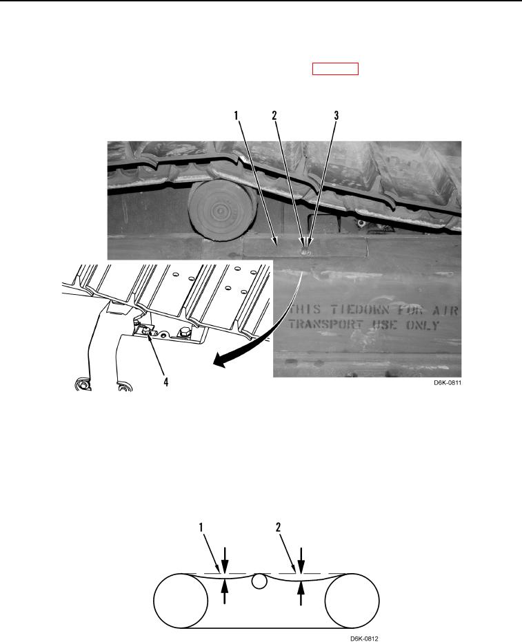
4. Remove bolt (Figure 16, Item 2), washer (Figure 16, Item 3), and plate (Figure 16, Item 1) from machine.
5. Add grease through valve (Figure 16, Item 4) until track tension meets specification 1.4 0.24 in. (35 6 mm).
If unable to tension track to specification, replace track adjuster (WP 0117).
6. Install plate (Figure 16, Item 1), washer (Figure 16, Item 3), and bolt (Figure 16, Item 2) on machine.
Figure 16. Track Tension Adjustment.
0112
Tight Track Adjustment
000112
1. Attach and stretch string from final drive to front Idler.
2. Measure track point (Figure 17, Item 1) and point (Figure 17, Item 2). Average these two measurements.
3. Track tension specification is 1.4 0.24 in. (35 6 mm).
Figure 17. Track Tension.
0112