
10
TM 5-2410-240-23-2
FIELD MAINTENANCE
-
TRACK ROLLER FRAME COVER AND GUARD REPLACEMENT
0113
Front Track Guard Removal, Front Idler Guard Removal, Front Track Roller Cover Removal,
Middle Track Roller Cover Removal, Sprocket Guard Removal, Cleaning and Inspection,
Sprocket Guard Installation, Middle Track Roller Cover Installation, Front Track Roller Cover
Installation, Front Idler Guard Installation, Front Track Guard Installation
INITIAL SETUP
Tools and Special Tools
Equipment Conditions
0
0
Tool Kit, General Mechanic's
Machine parked (TM 5-2410-240-10)
0
(WP 0289, Item 51)
0
Drawings Required
0
Materials/Parts
TM 5-2410-240-24P, Figure 47, 48, 49, 55
0
0
Rag, wiping (WP 0290, Item 21)
0
Estimated Time to Complete
0
References
2.0 Hr
0
0
WP 0282
0
0
FRONT TRACK GUARD REMOVAL
000113
N OT E
The following procedure is for the right outer front guard. Use the same procedure for right
inner, left inner, and left outer front guards.
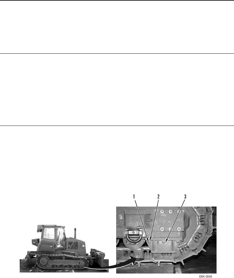
Note position of square spacers to aid installation. Beveled surface of spacer must be
installed toward weld.
Remove four bolts (Figure 1, Item 1), spacers (Figure 1, Item 2), and guard (Figure 1, Item 3) from machine.
Figure 1. Front Track Guard.
0113
END OF TASK