
TM 5-2410-240-23-2
0119
INSTALLATION
000119
WARN I N G
Use extreme caution when handling heavy parts. Provide adequate support and use
assistance during procedure. Ensure any lifting device used is in good condition and of
suitable load capacity. Keep clear of heavy parts supported only by lifting device. Failure
to follow this warning may result in injury or death to personnel.
N OT E
Use guide studs created during removal.
Procedure shows right final drive assembly. Follow the same steps for left final drive
assembly.
Final drive assembly weighs approximately 1,225 lb (556 kg).
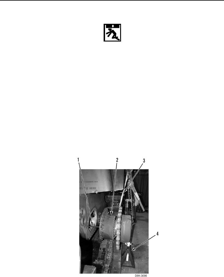
1. Install two guide studs (Figure 5, Item 1) on machine.
2. Install lifting device on inner and outer final drive assembly (Figure 5, Item 2).
3. Using lifting device, install final drive assembly (Figure 5, Item 2) on two guide studs (Figure 5, Item 1) and
support final drive assembly with jack stand (Figure 5, Item 4).
4. Remove lifting device (Figure 5, Item 3) only from inner portion of final drive (Figure 5, Item 2).
5. Using lifting device, remove jack stand (Figure 5, Item 4) and slide final drive assembly (Figure 5, Item 2), on
machine.
Figure 5. Final Drive Install.
0119