
TM 5-2410-240-23-2
0121
INSTALLATION CONTINUED
4. Install hand hydraulic pump (Figure 12, Item 1) on track brake (Figure 12, Item 2). Release track brake piston.
WARN I N G
Use extreme caution when handling heavy parts. Provide adequate support and use
assistance during procedure. Failure to follow this warning may result in injury or death to
personnel.
N OT E
The track brake weighs approximately 62 lb (28 kg).
5. With assistance, install track brake (Figure 12, Item 2), six washers (Figure 12, Item 4),and bolts (Figure 12,
Item 5) on machine.
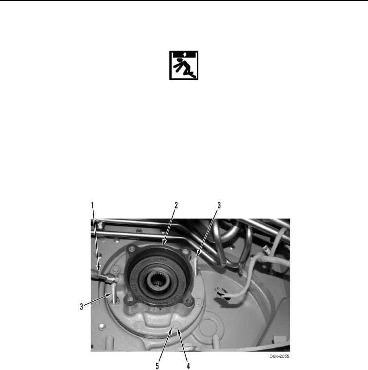
6. Remove two guide studs (Figure 12, Item 3) and hand hydraulic pump (Figure 12, Item 1) from track brake
(Figure 12, Item 2).
Figure 12. Track Brake Guide Studs.
0121