
TM 5-2410-240-23-2
0124
INSTALLATION CONTINUED
N OT E
Remove caps or plugs from hoses, lines, and fittings.
Install hoses and lines as noted during removal.
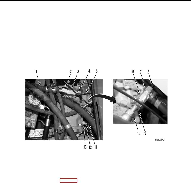
21. Connect hose (Figure 14, Item 11) on fitting (Figure 14, Item 13) and tighten tube nut (Figure 14, Item 12).
22. Connect hose (Figure 14, Item 10) on fitting (Figure 14, Item 6) and tighten tube nut (Figure 14, Item 9).
23. Connect line (Figure 14, Item 8) on fitting (Figure 14, Item 6) and tighten tube nut (Figure 14, Item 7).
24. Connect line (Figure 14, Item 5) on fitting (Figure 14, Item 3) and tighten tube nut (Figure 14, Item 4).
25. Connect hose (Figure 14, Item 1) on fitting (Figure 14, Item 3) and tighten tube nut (Figure 14, Item 2).
Figure 14. Hoses and Lines on Implement Pump.
0124
END OF TASK
FOLLOW-ON TASKS
000124
1. Install hydraulic fan gear pump (WP 0123).
2. Verify correct operation of machine (TM 5-2410-240-10).
END OF TASK
END OF WORK PACKAGE