
TM 5-2410-240-23-2
0130
REMOVAL CONTINUED
N OT E
Mark position and routing of hoses and lines to aid installation.
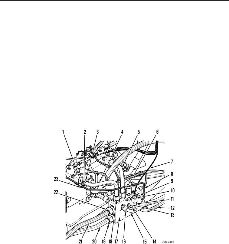
9. Remove nut (Figure 4, Item 23) and bolt (Figure 4, Item 1), two washers (Figure 4, Item 2), and clamps
(Figure 4, Item 3) from machine.
10. Loosen tube nut (Figure 4, Item 18) and remove line (Figure 4, Item 4) from manifold (Figure 4, Item 17).
11. Loosen tube nut (Figure 4, Item 6) and remove line (Figure 4, Item 5) from manifold (Figure 4, Item 17).
12. Loosen tube nut (Figure 4, Item 10) and remove hose (Figure 4, Item 7) from manifold (Figure 4, Item 17).
13. Loosen tube nut (Figure 4, Item 9) and remove line (Figure 4, Item 8) from manifold (Figure 4, Item 17).
14. Loosen tube nut (Figure 4, Item 11) and remove hose (Figure 4, Item 12) from manifold (Figure 4, Item 17).
15. Loosen tube nut (Figure 4, Item 16) and remove hose (Figure 4, Item 15) from manifold (Figure 4, Item 17).
16. Loosen tube nut (Figure 4, Item 19) and remove line (Figure 4, Item 20) from manifold (Figure 4, Item 17).
17. Loosen tube nut (Figure 4, Item 22) and remove line (Figure 4, Item 21) from manifold (Figure 4, Item 17).
18. Remove three bolts (Figure 4, Item 14), washer (Figure 4, Item 13) and manifold (Figure 4, Item 17) from
machine.
Figure 4. Manifold Hoses.
0130