
TM 5-2410-240-23-2
0130
REMOVAL
000130
WARN I N G
Hydraulic oil is very slippery. Immediately wipe up any spills. Failure to follow this warning
may result in injury to personnel.
N OT E
Mark position and routing of hoses and lines to aid installation.
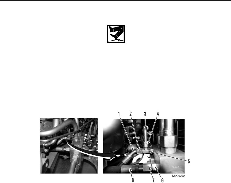
1. Loosen tube nut (Figure 1, Item 2) and remove hose (Figure 1, Item 1) from fitting (Figure 1, Item 5).
2. Loosen tube nut (Figure 1, Item 4) and remove hose (Figure 1, Item 3) from fitting (Figure 1, Item 5).
3. Loosen tube nut (Figure 1, Item 7) and remove hose (Figure 1, Item 8) from fitting (Figure 1, Item 6).
Figure 1. Left Motor Hose to Manifold.
0130