
TM 5-2410-240-23-2
0130
REMOVAL CONTINUED
N OT E
Mark position and routing of hoses and lines to aid installation.
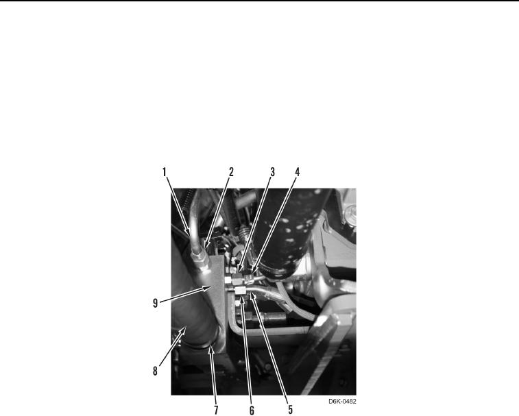
4. Loosen tube nut (Figure 2, Item 2) and remove line (Figure 2, Item 1) from manifold (Figure 2, Item 9).
5. Loosen tube nut (Figure 2, Item 3) and remove line (Figure 2, Item 4) from manifold (Figure 2, Item 9).
6. Loosen tube nut (Figure 2, Item 6) and remove hose (Figure 2, Item 5) from manifold (Figure 2, Item 9).
7. Loosen clamp (Figure 2, Item 7) and remove hose (Figure 2, Item 8) from manifold (Figure 2, Item 9).
Figure 2. Right Motor Hose To Manifold.
0130