
TM 5-2410-240-23-2
0130
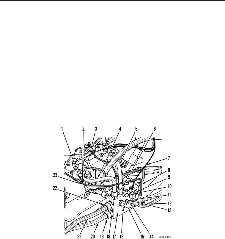
INSTALLATION CONTINUED
N OT E
Install hoses and lines as noted during removal.
2. Install manifold (Figure 12, Item 17), three washers (Figure 12, Item 13) and bolts (Figure 12, Item 14) on
machine.
3. Install two clamps (Figure 12, Item 3), washers (Figure 12, Item 2), bolt (Figure 12, Item 1) and nut (Figure 12,
Item 23) on machine.
4. Install line (Figure 12, Item 21) and tube nut (Figure 12, Item 22) on manifold (Figure 12, Item 17).
5. Install line (Figure 12, Item 20) and tube nut (Figure 12, Item 19) on manifold (Figure 12, Item 17).
6. Install hose (Figure 12, Item 15) and tube nut (Figure 12, Item 16) on manifold (Figure 12, Item 17).
7. Install hose (Figure 12, Item 12) and tube nut (Figure 12, Item 11) on manifold (Figure 12, Item 17).
8. Install line (Figure 12, Item 8) and tube nut (Figure 12, Item 9) on manifold (Figure 12, Item 17).
9. Install hose (Figure 12, Item 7) and tube nut (Figure 12, Item 10) on manifold (Figure 12, Item 17).
10. Install line (Figure 12, Item 5) and tube nut (Figure 12, Item 6) on manifold (Figure 12, Item 17).
11. Install line (Figure 12, Item 4) and tube nut (Figure 12, Item 18) on manifold (Figure 12, Item 17).
Figure 12. Pump Hoses.
0130