
TM 5-2410-240-23-2
0130
INSTALLATION CONTINUED
N OT E
Install hoses and lines as noted during removal.
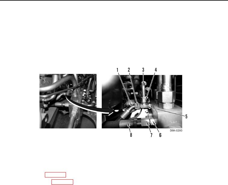
17. Install hose (Figure 15, Item 8) and tube nut (Figure 15, Item 7) on fitting (Figure 15, Item 6).
18. Install hose (Figure 15, Item 3) and tube nut (Figure 15, Item 4) on fitting (Figure 15, Item 5).
19. Install hose (Figure 15, Item 1) and tube nut (Figure 15, Item 2) on fitting (Figure 15, Item 5).
Figure 15. Left Motor Hose to Manifold.
0130
END OF TASK
FOLLOW-ON TASKS
000130
1. Fill hydraulic fluid (WP 0160).
2. Install bottom guards (WP 0156).
3. Verify correct operation of machine (TM 5-2410-240-10).
END OF TASK
END OF WORK PACKAGE