
TM 5-2410-240-23-2
0130
INSTALLATION CONTINUED
N OT E
Install hoses and lines as noted during removal.
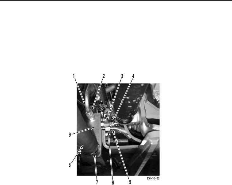
12. Install hose (Figure 13, Item 8) and clamp (Figure 13, Item 7) on manifold (Figure 13, Item 9).
13. Install hose (Figure 13, Item 5) and tube nut (Figure 13, Item 6) on manifold (Figure 13, Item 9).
14. Install line (Figure 13, Item 4) and tube nut (Figure 13, Item 3) on manifold (Figure 13, Item 9).
15. Install line (Figure 13, Item 1) and tube nut (Figure 13, Item 2) on manifold (Figure 13, Item 9).
Figure 13. Right Motor Hose to Manifold.
0130