
TM 5-2410-240-23-2
0131
REMOVAL
000131
N OT E
The following procedure will remove one hydraulic control manifold solenoid. Follow the
same procedure for additional hydraulic control manifold solenoid.
Tag and mark connectors to aid installation.
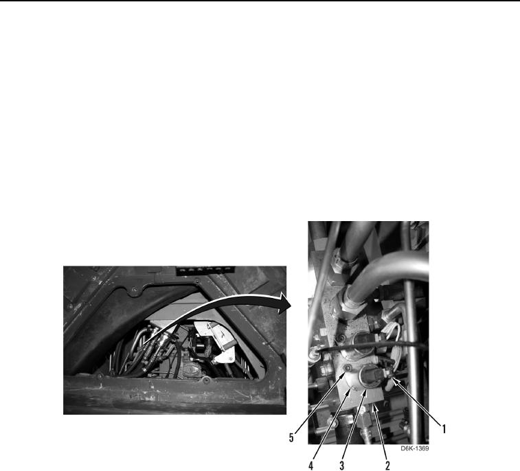
1. Disconnect harness connector (Figure 1, Item 1) from hydraulic control manifold solenoid (Figure 1, Item 3).
N OT E
Hydraulic oil will drain from control manifold when solenoid is removed.
2. Remove bolt (Figure 1, Item 5), clamp (Figure 1, Item 4) and hydraulic control manifold solenoid (Figure 1,
Item 3) from hydraulic control manifold (Figure 1, Item 2).
Figure 1. Hydraulic Control Manifold Solenoid.
0131