
TM 5-2410-240-23-2
0132
REMOVAL
000132
WARN I N G
Hydraulic oil is very slippery. Immediately wipe up any spills. Failure to follow this warning
may result in injury to personnel.
N OT E
This procedure will remove one hydrostatic pump solenoid valve. Follow the same
procedure for additional hydrostatic pump solenoid valves.
Note position and routing of electrical harness to aid installation.
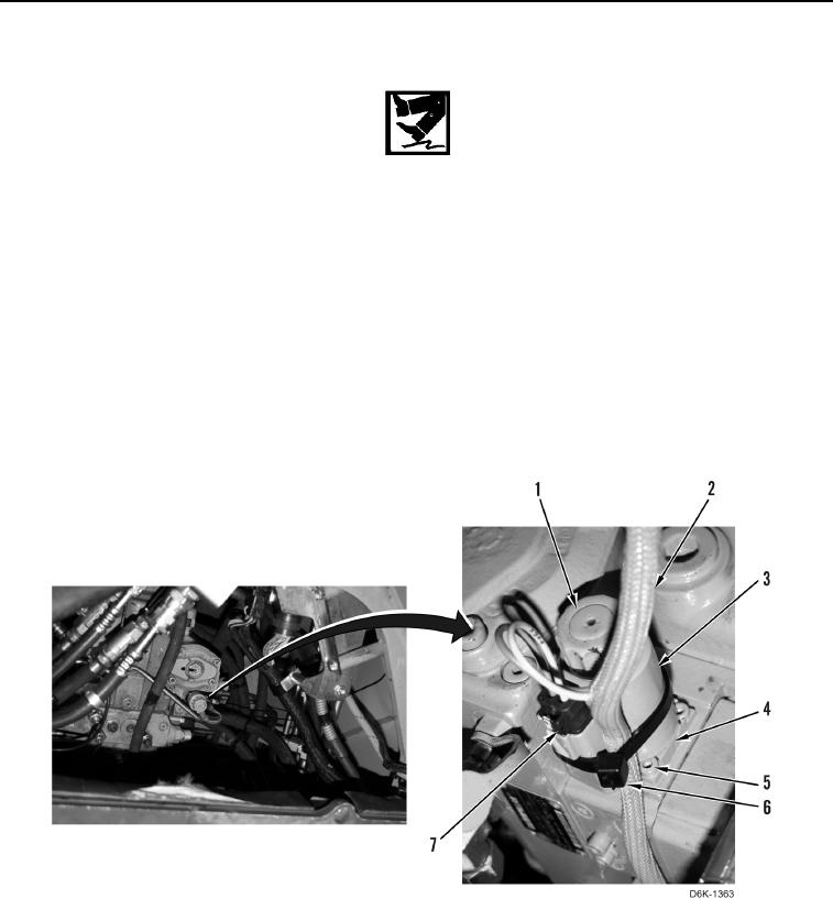
1. Disconnect connector (Figure 1, Item 7) from solenoid valve (Figure 1, Item 3).
2. Remove tiedown strap (Figure 1, Item 6) from solenoid valve (Figure 1, Item 3).
3. Position harness (Figure 1, Item 2) aside.
4. Remove cap (Figure 1, Item 1) and solenoid (Figure 1, Item 3) from valve (Figure 1, Item 4).
5. Remove four bolts (Figure 1, Item 5) and valve (Figure 1, Item 4) from machine.
Figure 1. Hydrostatic Pump Solenoid Valve.
0132
END OF TASK