• Home
  • Download PDF
  • Order CD-ROM
  • Order in Print
Figure 2. Hydraulic Control Manifold Solenoid O-rings.
Figure 4. Hydraulic Control Manifold Solenoid.

Field Maintenance Manual 2 D6K Dozer Type I With Winch and Type II With Ripper
Page Navigation
  755    756    757    758    759  760  761    762    763    764    765  
img
.
TM 5-2410-240-23-2
0131
INSTALLATION
000131
N OT E
The following procedure will install one hydraulic control manifold solenoid. Follow the
same procedure for additional hydraulic control manifold solenoid.
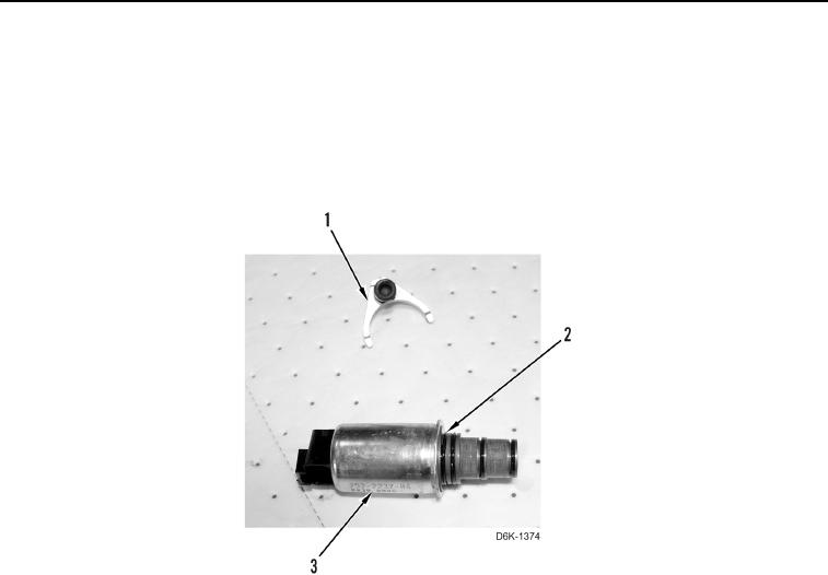
1. Install four new O-rings (Figure 3, Item 2) and clamp (Figure 3, Item 1) on hydraulic control manifold solenoid
(Figure 3, Item 3).
Figure 3. Hydraulic Control Manifold Solenoid O-rings.
0131
0131-4


Privacy Statement
Press Release
Contact

© Copyright Integrated Publishing, Inc.. All Rights Reserved.