
TM 5-2410-240-23-2
0131
INSTALLATION CONTINUED
N OT E
Install connectors as noted during removal.
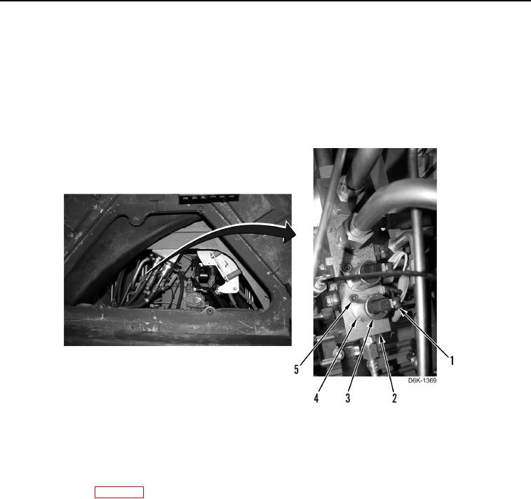
2. Install hydraulic control manifold solenoid (Figure 4, Item 3), clamp (Figure 4, Item 4), and bolt (Figure 4,
Item 5) on hydraulic control manifold (Figure 4, Item 2).
3. Connect harness connector (Figure 4, Item 1) on hydraulic control manifold solenoid (Figure 4, Item 3).
Figure 4. Hydraulic Control Manifold Solenoid.
0131
END OF TASK
FOLLOW-ON TASKS
000131
1. Fill hydraulic oil (WP 0160).
2. Install front floor plate (WP 0205).
3. Verify correct operation of machine (TM 5-2410-240-10).
END OF TASK
END OF WORK PACKAGE
0131-5/(6 blank)