
TM 5-2410-240-23-2
0134
REMOVAL CONTINUED
N OT E
Tag and mark hoses and fittings to aid installation.
Use a container to catch any fluid that may drain from hoses or system. Dispose of fluid
IAW local policy and ordinances. Ensure all spills are cleaned up.
Cap or plug hoses, fittings, and open ports.
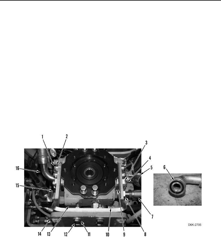
10. Remove four bolts (Figure 6, Item 1) and spacers (Figure 6, Item 2) from bracket (Figure 6, Item 15).
11. Remove four bolts (Figure 6, Item 12) and washers (Figure 6, Item 11) from pump support (Figure 6, Item 14).
12. Remove bracket (Figure 6, Item 15) from right hydrostatic drive piston pump (Figure 6, Item 13) and pump
support (Figure 6, Item 14).
13. Remove eight bolts (Figure 6, Item 4), washers (Figure 6, Item 3), four clamps (Figure 6, Item 9), and two
hoses (Figure 6, Items 5 and 16) from right hydrostatic drive piston pump (Figure 6, Item 13).
14. Remove two O-rings (Figure 6, Item 6) from hoses (Figure 6, Items 5 and 16). Discard O-rings. Position left
hose aside. Remove right hose from machine.
15. Loosen tube nut (Figure 6, Item 8) and disconnect hose (Figure 6, Item 7) from right hydrostatic drive piston
pump (Figure 6, Item 13). Position hose aside.
16. Using hydraulic line remover tool, disconnect hose (Figure 6, Item 10) from right hydrostatic drive piston pump
(Figure 6, Item 13). Position hose aside.
Figure 6. Retaining Hardware and Hoses on Right Hydrostatic Piston Pump.
0134