
TM 5-2410-240-23-2
0134
REMOVAL CONTINUED
N OT E
Tag and mark tubes and fittings to aid installation.
Cap or plug tubes and fittings.
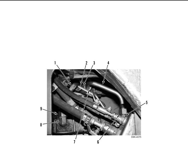
8. Loosen two tube nuts (Figure 5, Items 7 and 6) and disconnect tube (Figure 5, Item 4) from fitting (Figure 5,
Item 5) and transmission control manifold (Figure 5, Item 3). Remove tube from machine.
9. Loosen two tube nuts (Figure 5, Items 2 and 9) and disconnect tube (Figure 5, Item 1) from fitting (Figure 5,
Item 8) and transmission control manifold (Figure 5, Item 3). Remove tube from machine.
Figure 5. Tube on Left and Right Hydrostatic Drive Piston Pump and Transmission Control Manifold.
0134