
TM 5-2410-240-23-2
0134
REMOVAL
000134
N OT E
Note location of tiedown straps to aid installation.
Tag and mark electrical connectors to aid installation.
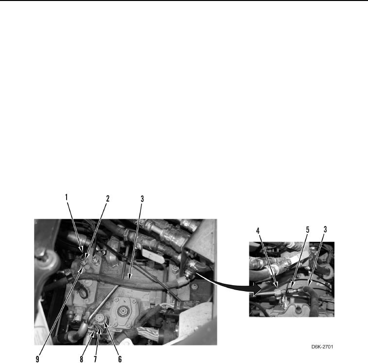
1. Remove tiedown strap (Figure 1, Item 8) from harness (Figure 1, Item 7) and solenoid (Figure 1, Item 6).
Discard tiedown strap.
2. Disconnect harness (Figure 1, Item 7) from solenoid (Figure 1, Item 6).
N OT E
Tag and mark hose, lines, and fittings to aid installation.
Cap or plug hose, lines, and fittings.
3. Loosen two tube nuts (Figure 1, Item 2) and disconnect lines (Figure 1, Item 1) from fittings (Figure 1, Item 9).
Position lines aside.
4. Loosen tube nut (Figure 1, Item 5) and disconnect hose (Figure 1, Item 3) from fitting (Figure 1, Item 4).
Position hose aside.
Figure 1. Harness, Lines, and Hose Connections on Left and Right Hydraulic Drive Piston Pump.
0134