
TM 5-2410-240-23-2
0136
INSTALLATION CONTINUED
N OT E
Install wiring harnesses and electrical connectors as noted during removal.
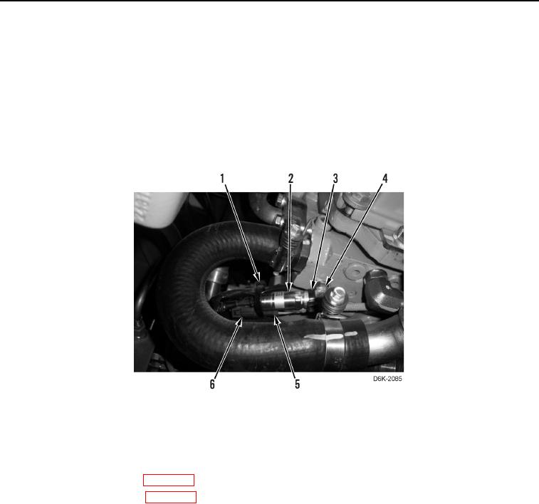
3. Connect sensor harness (Figure 4, Item 6) to solenoid harness (Figure 4, Item 5).
4. Install new tiedown strap (Figure 4, Item 3) on fitting (Figure 4, Item 4) and solenoid harness (Figure 4, Item 5).
5. Install new tiedown strap (Figure 4, Item 1) on winch oil pressure sensor (Figure 4, Item 2), solenoid harness
(Figure 4, Item 5), and sensor harness (Figure 4, Item 6).
Figure 4. Winch Oil Pressure Sensor, Sensor Harness, Solenoid Harness, and Retaining Hardware.
0136
END OF TASK
FOLLOW-ON TASKS
000136
1. Install rear bottom guards (WP 0156).
2. Check hydraulic fluid level (WP 0160).
3. Verify correct operation of machine (TM 5-2410-240-10).
END OF TASK
END OF WORK PACKAGE
0136-5/(6 blank)