
TM 5-2410-240-23-2
0140
INSTALLATION CONTINUED
N OT E
Install electrical connectors as noted during removal.
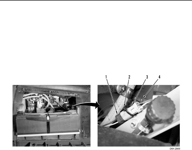
9. Connect lockout switch connector (Figure 9, Item 3) to chassis harness connector (Figure 9, Item 1).
N OT E
Install tiedown straps as noted during removal.
10. Install new tiedown strap (Figure 9, Item 2) on clip (Figure 9, Item 4) and lockout switch connector (Figure 9,
Item 3).
Figure 9. Lockout Switch Connector.
0140
END OF TASK
FOLLOW-ON TASKS
000140
1. Install right rear access cover (WP 0191).
2. Verify correct operation of machine (TM 5-2410-240-10).
END OF TASK
END OF WORK PACKAGE
0140-7/(8 blank)