
TM 5-2410-240-23-2
0140
INSTALLATION
000140
1. Install washer (Figure 5, Item 1) on lockout switch (Figure 5, Item 2).
2. Open lockout switch access door (TM 5-2410-240-10).
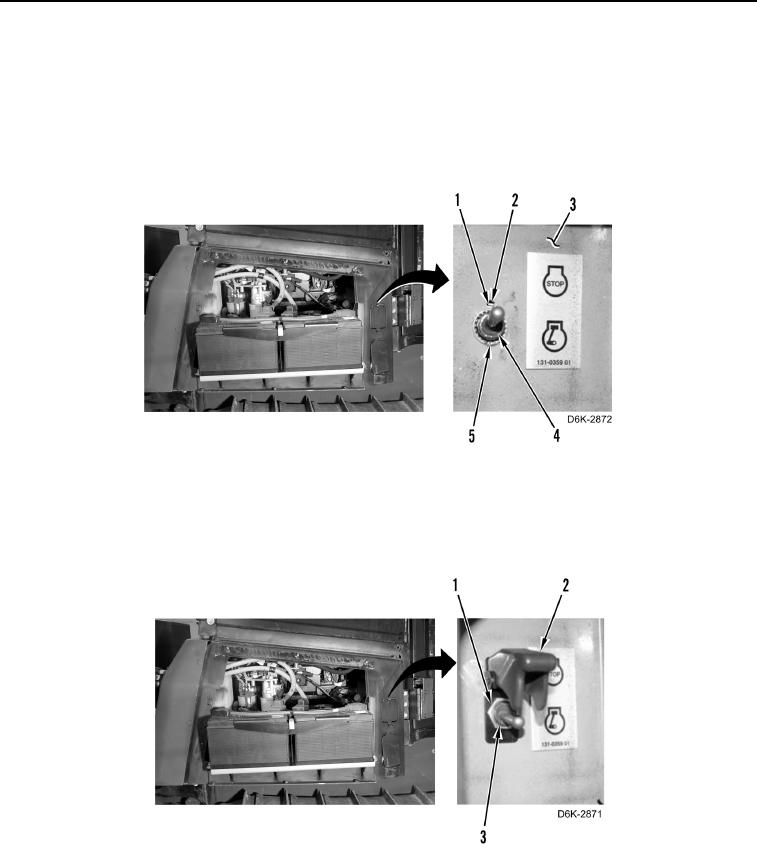
3. Install lockout switch (Figure 6, Item 4) on machine (Figure 6, Item 3) and seat washer tab (Figure 6, Item 1) in
hole (Figure 6, Item 2).
4. Install new lockwasher (Figure 6, Item 5) on lockout switch (Figure 6, Item 4).
Figure 6. Lockwasher and Lockout Switch.
0140
5. Install guard (Figure 7, Item 2) and nut (Figure 7, Item 1) on lockout switch (Figure 7, Item 3).
6. Position guard (Figure 7, Item 2) downward.
Figure 7. Lockout Switch and Guard.
0140
7. Close lockout switch access door (TM 5-2410-240-10).