
8
TM 5-2410-240-23-2
FIELD MAINTENANCE
-
LOCKOUT SWITCH REPLACEMENT
014
0
Removal, Cleaning and Inspection, Installation
INITIAL SETUP
References
Tools and Special Tools
0
0
Tool Kit, General Mechanic's
WP 0282
0
(WP 0289, Item 51)
0
Equipment Conditions
0
Materials/Parts
Machine parked (TM 5-2410-240-10)
0
0
Rag, wiping (WP 0290, Item 21)
Right rear access cover removed (WP 0191)
0
0
Tag, marker (WP 0290, Item 30)
0
Drawings Required
0
Tiedown strap (WP 0290, Item 31)
0
TM 5-2410-240-24P, Figure 66
Lockwasher
0
0
Estimated Time to Complete
0
0.5 Hr
0
REMOVAL
000140
N OT E
Note location of tiedown straps to aid installation.
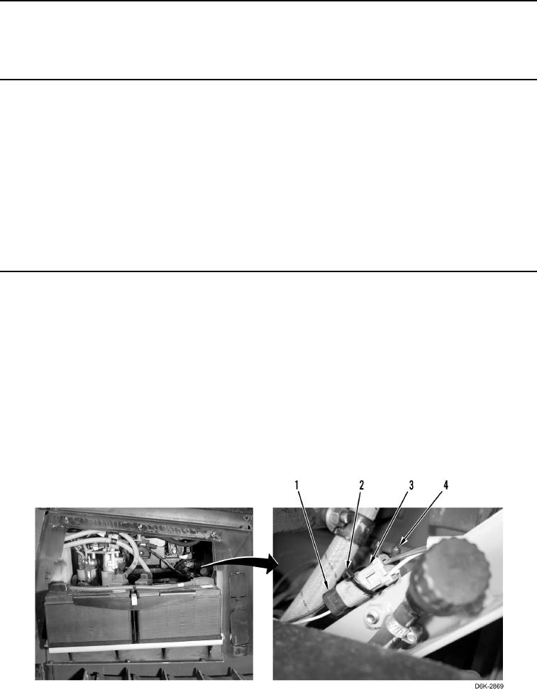
1. Remove tiedown strap (Figure 1, Item 2) from lockout switch connector (Figure 1, Item 3) and clip (Figure 1,
Item 4). Discard tiedown strap.
N OT E
Tag and mark electrical connectors to aid installation.
2. Disconnect lockout switch connector (Figure 1, Item 3) from chassis harness connector (Figure 1, Item 1).
Figure 1. Lockout Switch Connector.
0140