
2
TM 5-2410-240-23-2
FIELD MAINTENANCE
-
HORN REPLACEMENT
01
39
Removal, Cleaning and Inspection, Installation
INITIAL SETUP
Tools and Special Tools
References
0
0
Tool Kit, General Mechanic's
WP 0282
0
(WP 0289, Item 51)
0
Equipment Conditions
0
Materials/Parts
Machine parked (TM 5-2410-240-10)
0
0
Rag, wiping (WP 0290, Item 21)
0
Drawings Required
0
Tag, marker (WP 0290, Item 30)
0
TM 5-2410-240-24P, Figure 65
0
Estimated Time to Complete
0
0.5 Hr
0
REMOVAL
000139
1. Unlatch and open upper radiator grill (TM 5-2410-240-10).
N OT E
Tag and mark electrical connector to aid installation.
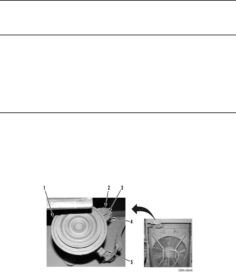
2. Disconnect harness connector (Figure 1, Item 5) from horn (Figure 1, Item 1).
3. Remove bolt (Figure 1, Item 2), washer (Figure 1, Item 3), and horn (Figure 1, Item 1) from bracket (Figure 1,
Item 4).
Figure 1. Horn and Retaining Hardware.
0139
END OF TASK