
TM 5-2410-240-23-2
0138
INSTALLATION CONTINUED
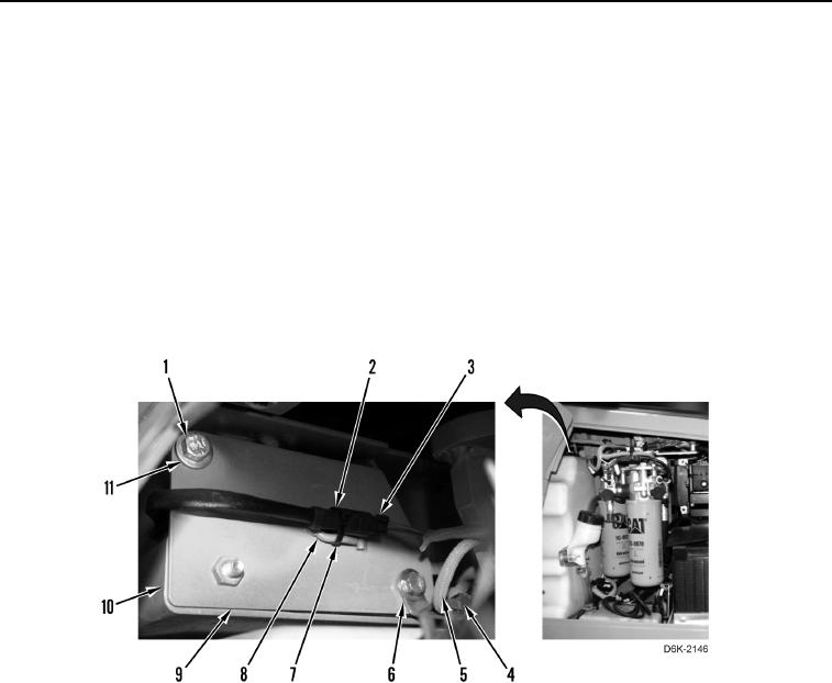
5. Position mounting plate (Figure 6, Item 9) on machine (Figure 6, Item 10).
6. Install clip (Figure 6, Item 6), two washers (Figure 6, Item 11), and bolts (Figure 6, Item 1) on mounting plate
(Figure 6, Item 9).
7. Install new tiedown strap (Figure 6, Item 4) and connecting harness (Figure 6, Item 5) on clip (Figure 6,
Item 6).
N OT E
Connect electrical connectors as noted during removal.
8. Connect backup alarm connector (Figure 6, Item 2) to chassis harness connector (Figure 6, Item 3).
9. Install new tiedown strap (Figure 6, Item 7) on clip (Figure 6, Item 8) and backup alarm connector (Figure 6,
Item 2).
Figure 6. Backup Alarm Connector and Mounting Plate.
0138
END OF TASK
FOLLOW-ON TASKS
000138
1. Install right rear access cover (WP 0191).
2. Verify correct operation of machine (TM 5-2410-240-10).
END OF TASK
END OF WORK PACKAGE
0138-5/(6 blank)