
TM 5-2410-240-23-2
0152
INSTALLATION
000152
N OT E
Install chassis harness, tiedown straps, and electrical connectors as noted during
removal.
1. Install middle chassis harness (Figure 4, Item 7) on machine.
2. Install clamp (Figure 4, Item 4) on chassis harness (Figure 4, Item 7).
3. Install clamp (Figure 4, Item 4), washer (Figure 4, Item 2), and bolt (Figure 4, Item 3) on bracket (Figure 4,
Item 6).
4. Connect and lock chassis harness (Figure 4, Item 7) to platform harness (Figure 4, Item 8).
5. Install new tiedown strap (Figure 4, Item 5) on bracket (Figure 4, Item 6), engine harness (Figure 4, Item 1),
and chassis harness (Figure 4, Item 7).
C AU T I O N
Install tiedown straps as noted during removal.
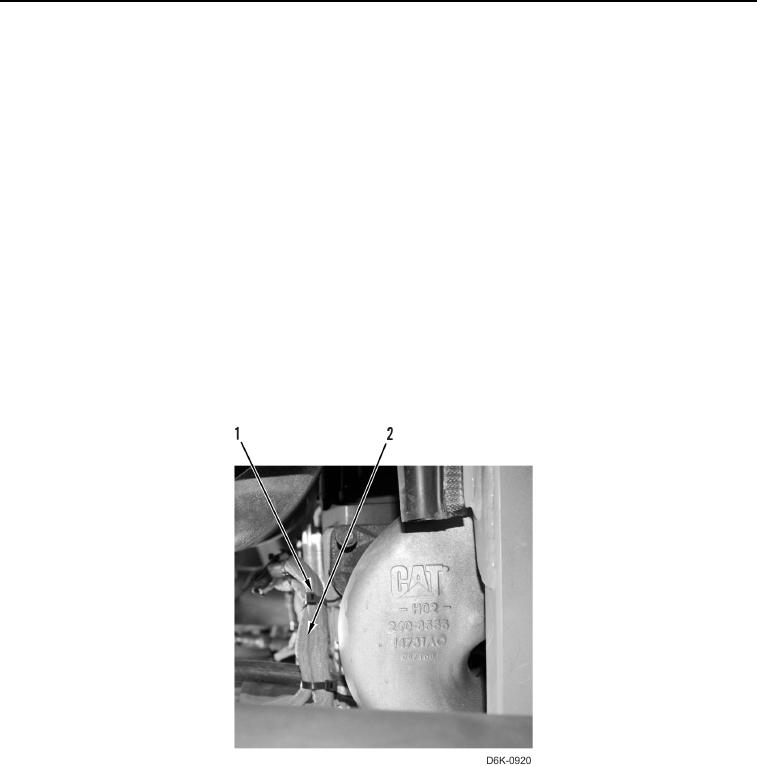
6. Install five new tiedown straps (Figure 5, Item 1) on chassis harness (Figure 5, Item 2).
Figure 5. Chassis Harness Retainers Behind Right Rear of Engine.
0152