• Home
  • Download PDF
  • Order CD-ROM
  • Order in Print
Figure 17. Hydraulic Oil Temperature Sensor and Chassis Harness on Side of Hydraulic Oil Tank.
Figure 19. Upper Access Plate and Retaining Hardware on Rear of Machine.

Field Maintenance Manual 2 D6K Dozer Type I With Winch and Type II With Ripper
Page Navigation
  1005    1006    1007    1008    1009  1010  1011    1012    1013    1014    1015  
img
.
TM 5-2410-240-23-2
0153
INSTALLATION CONTINUED
N OT E
Install tiedown straps and electrical connectors as noted during removal.
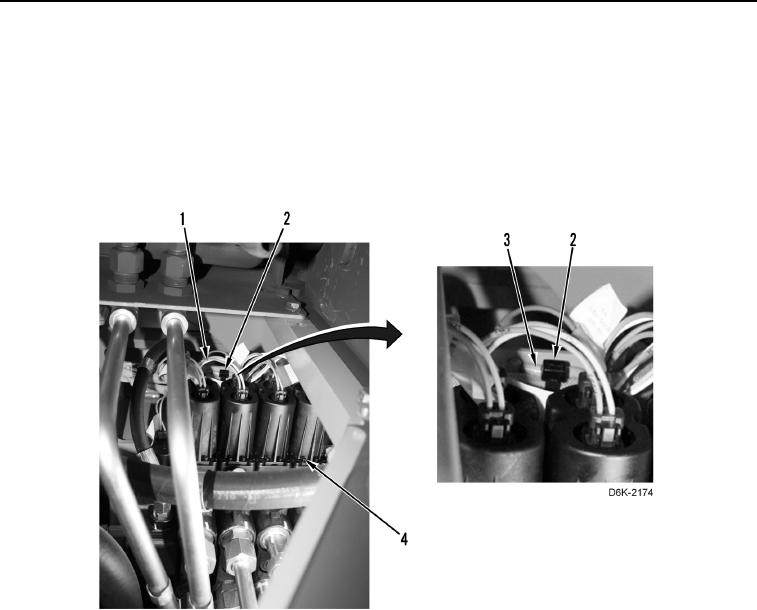
9. Connect chassis harness (Figure 18, Item 2) to nine solenoids (Figure 18, Item 1).
10. Install eight new tiedown straps (Figure 18, Item 3) on clips (Figure 18, Item 4) and chassis harness (Figure 18,
Item 2).
Figure 18. Solenoids, Chassis Harness, and Retaining Hardware at Rear of Machine.
0153
0153-17


Privacy Statement
Press Release
Contact

© Copyright Integrated Publishing, Inc.. All Rights Reserved.