
TM 5-2410-240-23-2
0153
INSTALLATION
000153
N OT E
Install chassis harness, tiedown straps, and electrical connectors as noted during
removal.
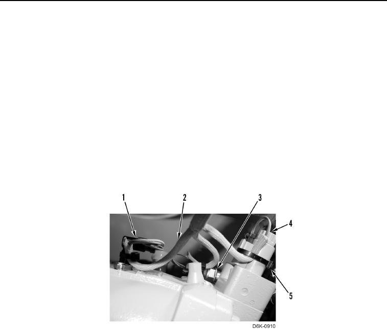
1. Install chassis harness (Figure 15, Item 2) on machine.
N OT E
Install tiedown straps and electrical connectors as noted during removal.
2. Connect chassis harness (Figure 15, Item 2) to solenoid (Figure 15, Item 4) and speed sensor (Figure 15,
Item 1).
3. Connect and lock chassis harness (Figure 15, Item 2) to pressure sensor (Figure 15, Item 3).
4. Install three new tiedown straps (Figure 15, Item 5) on chassis harness (Figure 15, Item 2), solenoid
(Figure 15, Item 4), pressure sensor (Figure 15, Item 3), and speed sensor (Figure 15, Item 1).
Figure 15. Solenoid, Pressure Sensor, Speed Sensor, Chassis Harness,
and Retaining Hardware at Left Hydrostatic Motor.
0153