• Home
  • Download PDF
  • Order CD-ROM
  • Order in Print
Figure 11. Solenoids, Chassis Harness, and Retaining Hardware at Rear of Machine.
Figure 13. Solenoid, Speed Sensor, Chassis Harness, and Retaining Hardware at Right Hydrostatic Motor

Field Maintenance Manual 2 D6K Dozer Type I With Winch and Type II With Ripper
Page Navigation
  999    1000    1001    1002    1003  1004  1005    1006    1007    1008    1009  
img
.
TM 5-2410-240-23-2
0153
REMOVAL CONTINUED
N OT E
Tag and mark electrical connectors to aid installation.
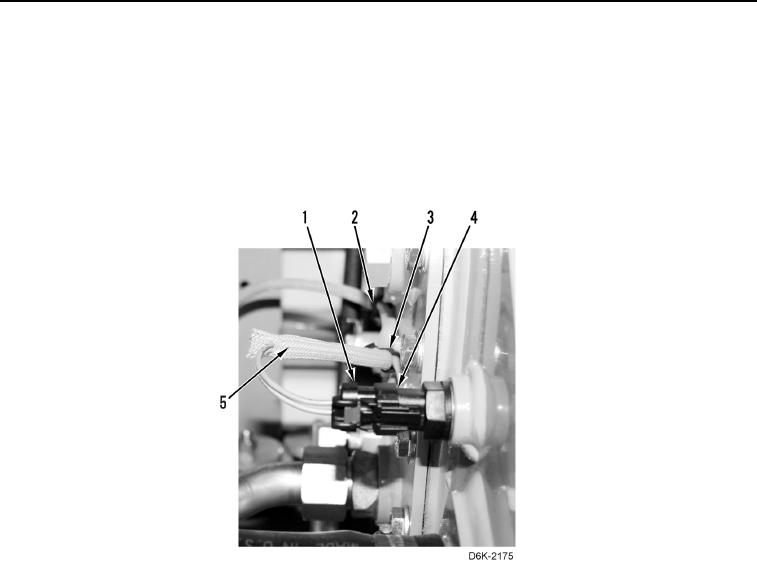
21. Unlock and disconnect chassis harness connector (Figure 12, Item 1) from hydraulic oil temperature sensor
(Figure 12, Item 4).
22. Remove tiedown straps (Figure 12, Items 2 and 3) from harness (Figure 12, Item 5).
Figure 12. Hydraulic Oil Temperature Sensor and Chassis Harness on Side of Hydraulic Oil Tank.
0153
0153-11


Privacy Statement
Press Release
Contact

© Copyright Integrated Publishing, Inc.. All Rights Reserved.