
TM 5-2410-240-23-2
0153
REMOVAL CONTINUED
N OT E
Note location of tiedown straps and tag and mark electrical connectors to aid installation.
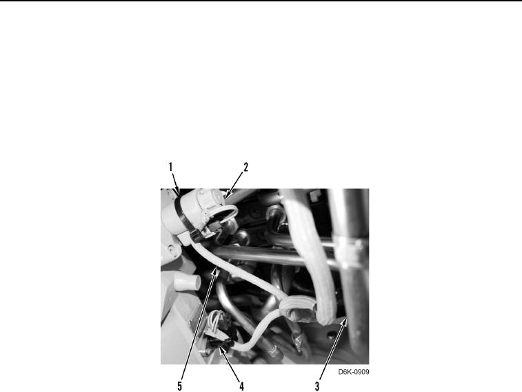
23. Disconnect chassis harness (Figure 13, Item 5) from solenoid (Figure 13, Item 2) and speed sensor (Figure 13,
Item 4).
24. Remove six tiedown straps (Figure 13, Item 1) from chassis harness (Figure 13, Item 5), solenoid (Figure 13,
Item 2), speed sensor (Figure 13, Item 4), and tubes (Figure 13, Item 3). Discard tiedown straps.
Figure 13. Solenoid, Speed Sensor, Chassis Harness, and Retaining Hardware at Right Hydrostatic Motor.
0153