• Home
  • Download PDF
  • Order CD-ROM
  • Order in Print
Figure 12. Hydraulic Oil Temperature Sensor, Solenoids, and Chassis Harness at Rear of Machine
Figure 14. Solenoid, Pressure Sensor, Speed Sensor, Chassis Harness, and Retaining Hardware at Left Hydrostatic Motor.

Field Maintenance Manual 2 D6K Dozer Type I With Winch and Type II With Ripper
Page Navigation
  1027    1028    1029    1030    1031  1032  1033    1034    1035    1036    1037  
img
.
TM 5-2410-240-23-2
0154
INSTALLATION CONTINUED
N OT E
Install electrical connectors and tiedown straps as noted during removal.
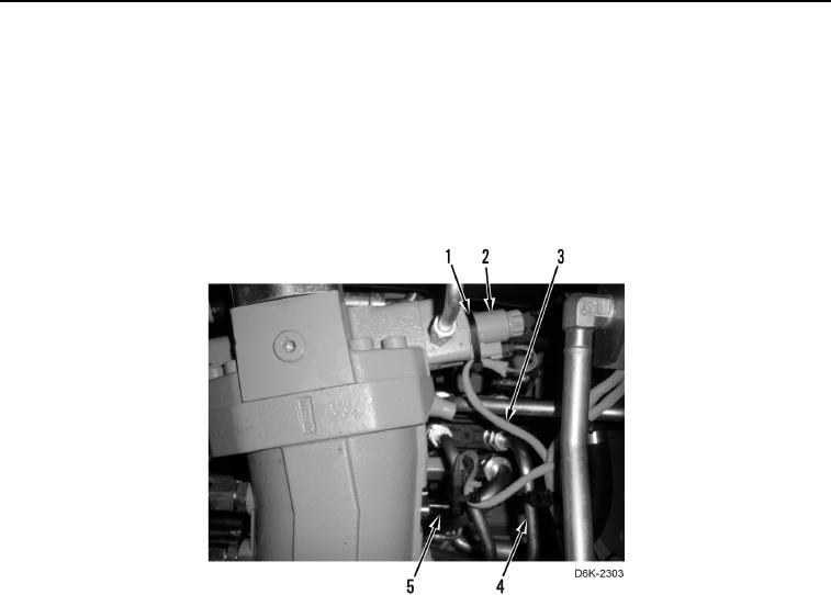
4. Connect chassis harness (Figure 13, Item 3) to solenoid (Figure 13, Item 2) and speed sensor (Figure 13,
Item 5).
5. Install six new tiedown straps (Figure 13, Item 1) on chassis harness (Figure 13, Item 3), solenoid (Figure 13,
Item 2), speed sensor (Figure 13, Item 5), and tubes (Figure 13, Item 4).
Figure 13. Solenoid, Speed Sensor, Chassis Harness, and Retaining Hardware
at Right Hydrostatic Motor.
0154
0154-13


Privacy Statement
Press Release
Contact

© Copyright Integrated Publishing, Inc.. All Rights Reserved.