
TM 5-2410-240-23-2
0154
INSTALLATION CONTINUED
N OT E
Install tiedown straps as noted during removal.
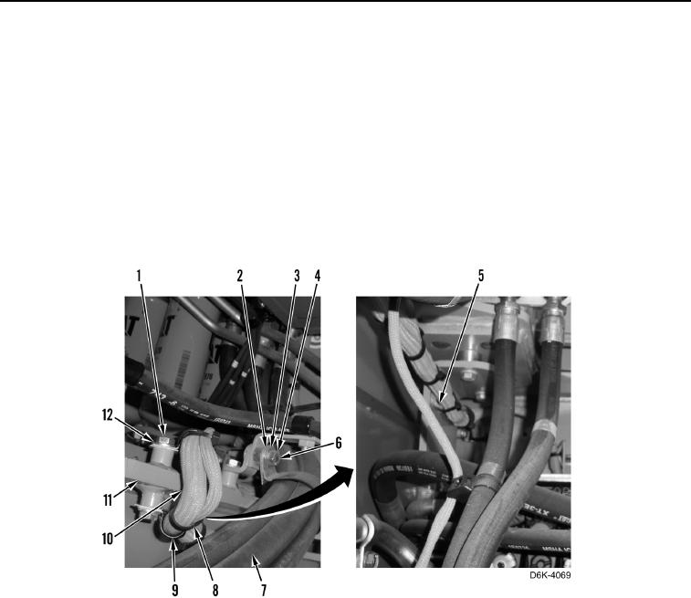
9. Install two clamps (Figure 15, Item 9) on chassis harness (Figure 15, Item 10).
10. Install two clamps (Figure 15, Item 9), washers (Figure 15, Item 12), and bolts (Figure 15, Item 1) on machine
(Figure 15, Item 11).
11. Position hoses (Figure 8, Item 7) and install clamp (Figure 8, Item 2), washer (Figure 8, Item 3), and nut
(Figure 8, Item 4) on stud (Figure 8, Item 6).
12. Install 33 new tiedown straps (Figure 15, Item 8) on chassis harness (Figure 15, Item 10) and clips (Figure 15,
Item 5).
Figure 15. Harness Retaining Hardware Inside Frame.
0154